
Featured article
Solutions


Products


Resources


Installation guide
Step four: review installation considerations and requirements
Electrical considerations
- The FW2000e must be three feet from any electrical light or standard electrical panel and at least twenty feet from overhead power lines.
- The FW2000e must be bonded to the utility ground.
- All aspects of the installation must be in full compliance with all applicable local and state codes.
- Avoid running the cable along other lines or conduit used for AC power, which can cause interference with data transfer through the cable.
Mounting considerations
- The FW2000e must be mounted a minimum of five feet above the walking surface and out of reach of small children.
- Mounting must also adhere to all FCC rules and regulations.
Roof mounting considerations
- Mounting on a sloped roof requires a structurally sound surface covered with asphalt shingles that can support the weight of the mount and the FW2000e. Other roofing material: metal, slate, tile, or shake may require extra support for secure mounting.
- Mount in an overhang section. Always avoid mounting over living spaces.
- At least two of the mounting screws must be secured in a rafter, and Bishop tape or tar-based sealant must be used for each mounting screw.
- Roofs with less than thirty-five-degree pitch may require the use of a non-standard mount such as a non-penetrating sled.
- Seal any penetrations used to bring cable inside with silicone.
Wall mounting considerations
- Mounting on a wall requires a structurally sound surface that can support the weight of the mount and the FW2000e. Recommended surfaces include: wood or wood-composite panel/lap siding, hollow cinder block, poured concrete, and brick. Other material: vinyl/steel/aluminum siding, covered brick, or stucco may require extra support for secure mounting.
NOTE: If metal siding is the only option available, a backer board can be used on the other side to provide a more secure mount.
- At least two screws lined up vertically must be attached to a structural element such as a wall stud, and all screws must be sealed with silicone for weatherproofing.
Cabling requirements
- Cable going from the FW3000 to the PoE must be outdoor rated, shielded Cat6A Ethernet cable, and provide an end-to-end connection from the FW3000 to the PoE power injector. The total length of cable must not exceed 300 feet in total length, including indoor cables.
NOTE: It is recommended that you keep the cable run at 250 feet or less and use a cable tester to verify connectivity at the time of installation.
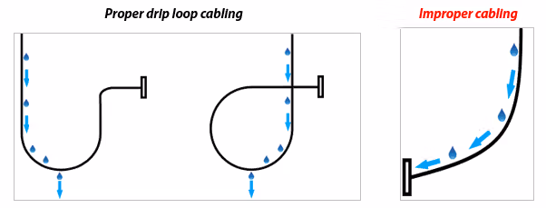
- Use drip/service loops to properly direct water away at the FW3000 and any penetration locations.
- Secure the cable using screw-type single flexible cable clips, nail clips, or vinyl siding clips.
NOTE: T50, T25, or other similar staples are not approved for exterior cable attachment, as they can damage the cable jacket and allow water to enter the cable. Using a flooded cable can help prevent water intrusion should the cable jacket become compromised.
- Run cable along building lines vertically or horizontally and attach it every 18-36 inches. Avoid running cable diagonally.
Grounding requirements
- The FW2000e must be properly bonded to an appropriate location such as the utility ground.
- The ground connection must be unique and not shared with another ground run.
- It is recommended to use #10 solid copper wire for the ground run from the FW2000e. Ensure the ground run is as short and straight as possible.
- Recommended ground/bond connections include:
- A building utility ground.
- A galvanized ground strap attached to a metal electrical raceway or conduit. Always use like materials for the strap and wire.
- An electrical panel clamp attached to the top or side of the metal electrical service panel. Ensure it does not impede opening of the service panel door.