
Featured case study


Installation guide
Step three: install the PoE cable
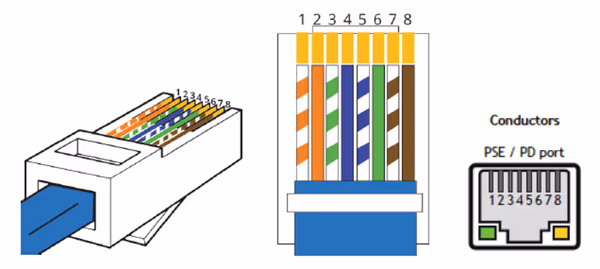
- If necessary, make sure your PoE cable wiring is correct. The recommended PoE cable is Cat6A with T568B on both ends.
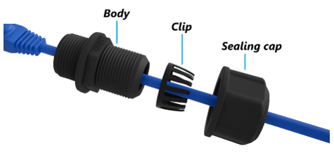
- Unscrew the PoE gland cap assembly.
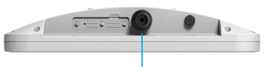
- Thread the PoE cable through the sealing cap, clip, and body of the gland assembly.
- Insert the connector into the FW2000e and screw the body of the gland to the FW2000e.
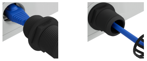
NOTE: When removing the cable from the FW2000e, use a thin tool such as a flathead screwdriver or pen to release the tab on the Ethernet plug.
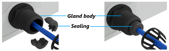
- Connect the two parts of the sealing around the cable, then slide the sealing into the gland body.
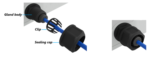
- Slide the clip and the sealing cap along the cable and screw the sealing cap tightly to the gland body. The sealing cap will keep the PoE connection secure and watertight.
- Insert the other end of the cable into the PoE injector Data & Power Out port. Plug the PoE injector into an earthed AC outlet. Consider using a surge protector when warranted.
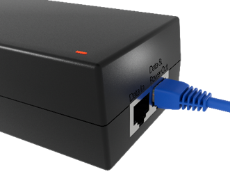
NOTE: The PoE injector status LED does not indicate data transmission. The LED is red when the FW2000e is connected. The LED is green when the FW2000e is NOT connected and there is no load.